|

|
|
| Ask the Experts | |||||||
|
|||||||
|
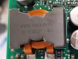
May 1, 2024 - Updated April 19, 2022 - Originally Posted Coils Rotated After Reflow
Y.I. |
|||||||
| Expert Panel Responses | |||||||
|
Is this being dragged round by internal baffles/curtains as its quite large?
Technical Sales Manager BLT Circuit Services Ltd Greg York has over thirty two years of service in Electronics industry. York has installed over 600 Lead Free Lines in Europe with Solder and flux systems as well as Technical Support on SMT lines and trouble shooting.
Possibly a high center point under the device. Verify that the device sits flat and favors the leads contacting on a flat surface. You may also use a Loctite staking material to prevent this issue.
Engineering Manager Circuit Technology Center, Inc. Manufacturing Engineer of 20+ years. Involved in Industries relating to all sectors of defense, Commercial product Industries, RF - Microwave and Semiconductor industries. Vast knowledge and experience relating Mil-STD’s, IPC-STD’s, EAI-STD’s, GEIA-STD’s, J-STD’s and MIL-PRF-STD’s.
This is a thermal issue, resulting from the reflow of the solder paste and the design of the termination beneath the component. If the pad is not symmetrical, as the solder melts the surface tension of the molten solder will pull the component to where the maximum amount of solder is situated on the land area. This will cause the component to move from its original placement. I suggest looking at the stencil and see where and how the paste is dispositioned beneath the component, and it may be worthwhile to rearrange the stencil openings to be more conducive to creating or allowing an even distribution of the solder paste on the board.
Vice President, Technical Director EPTAC Corporation At EPTAC Corporation, Mr. Lambert oversees content of course offerings, IPC Certification programs and provides customers with expert consultation in electronics manufacturing, including RoHS/WEEE and lead free issues. Leo is also the IPC General Chairman for the Assembly/Joining Process Committee.
There are 2 scenarios:
Director of Sales and Marketing Sierra Circuits Amit Bahl started to work at Sierra Circuits in 2006 where he formed strong relationships with his customers working with them on flex PCBs, HDI, controlled impedance, etc. In 2009, he was promoted Director of Sales and Marketing.
If the component is placed centered on pads, the reflow process can cause the part to "float" on the pads - pad design review can help with that but a simple adhesive dot under the part will eliminate the headaches.
Engineering and Operations Management Independent Consultant Georgian Simion is an independent consultant with 20+ years in electronics manufacturing engineering and operations.
Contact me at georgiansimion@yahoo.com. |
|||||||
| Submit A Comment | |||||||
|
Comments are reviewed prior to posting. You must include your full name to have your comments posted. We will not post your email address. |
|
Free Newsletter Subscription
Circuitnet is built for professionals who bear the responsibility of looking ahead, imagining the future, and preparing for it. Insert Your Email Address |
|

|


