|

|
|
| Ask the Experts | |||||||
|
|||||||
|
May 29, 2024 - Updated August 13, 2014 - Originally Posted MELF Component Misalignment
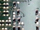
But all the chip components are correctly aligned. In testing if we eliminate the gluing of the MELF components there is no misalignment. What is happening? S.A. |
|||||||
| Expert Panel Responses | |||||||
|
In my opinion the glue in the middle of the MELF being raised is acting like a see-saw causing instability during curing. A "C" shaped paste aperture on the MELF helps self-align the device during reflow. If gluing is required I suggest a glue deposit with a gap in the center to help stabilize the MELF during curing.
Vice President Technology Photo Stencil For over 18 years, Dr. Coleman has been the vice president of technology for Photo Stencil, working closely with customers to understand their printing requirements. His efforts have resulted in several new stencil products.
It appears that you are curing the chip bonder epoxy during reflow. This will cure faster because the ramp rate is too fast of a cure for the epoxy and is hardening during the liquidus phase of the reflow and is realigning the parts.
President/Senior Technical Consultant Foresite Mr. Munson, President and Founder of Foresite, has extensive electronics industry experience applying Ion Chromatography analytical techniques to a wide spectrum of manufacturing applications.
If the absence of chipbonder corrects the problem, then the only root cause I can think of is that the MELF is twisting as the chipbonder slumps during curing. In looking at the picture it does not appear that there was any solder paste printed, although it is very hard to see for sure. Are you dispensing chipbonder, placing the part, curing, and then performing wave soldering or selective soldering rather than reflow? That would explain the chipbonder's ability to torque the component as it cures. Imagine placing a small rectangular paper box right on the very top of a Dairy Queen ice cream cone with the little swirl on top. As the ice cream melts, the swirl is going to twist down into the slumping material, and it will torque the paper box as it does due to the wetting tension. Same thing is probably happening with the MELF and the chipbonder, if there is no solder paste to help hold it in alignment. If the MELF is placed into solder paste and reflows just fine, perhaps you can get away with not using the chipbonder. If you have proven you can do this without Most Ending up Laying on the Floor, then I would do that. But you may need an engineering change order from your customer if the chipbonding is a requirement on the Assembly Drawing. A larger quantity may need to first be qualified to verify you are not going to have issues such as an increase in tombstoning or shifted parts after reflow. You don't want to trade one issue for another. If an engineering change order is allowed, make the chipbonder optional. At the various companies I work for, none perform chipbonding as a general rule. They have zero issues when depending on the surface tension of the molten solder to align the part during reflow. If you HAVE to dispense chipbonder, perhaps you can modify the dispense program to add a change of direction or a pause after the dispense tip goes up in the Z-axis to eliminate the swirl or stringing. But there may not be a swirl, it may just be the material's natural tendency. You can also try a different chipbonder to see if a different material eliminates the issue.
Advanced Engineer/Scientist General Dynamics Richard D. Stadem is an advanced engineer/scientist for General Dynamics and is also a consulting engineer for other companies. He has 38 years of engineering experience having worked for Honeywell, ADC, Pemstar (now Benchmark), Analog Technologies, and General Dynamics.
Not being sure of the process, but I imagine this is all being done in a sequential fashion, with the solder paste being applied first, then the adhesive, then the component placement, then reflowed. My guess would be the adhesive has a higher surface tension than the molten solder, so as the adhesive cures you could have competing surface energies between the molten solder and the liquid adhesive. Once the adhesive cures and solidifies, it is capturing a larger area of the circular component than the solder captures on the termination ends, and the component moves before the solder solidifies. When the adhesive is removed from the process, there is no competition between the two surface energies and the solder realigns the components on the center of the pads. There is lots of math involved in this theory, but I'm sure it can be figured out mathematically.
Vice President, Technical Director EPTAC Corporation At EPTAC Corporation, Mr. Lambert oversees content of course offerings, IPC Certification programs and provides customers with expert consultation in electronics manufacturing, including RoHS/WEEE and lead free issues. Leo is also the IPC General Chairman for the Assembly/Joining Process Committee.
|
|||||||
| Submit A Comment | |||||||
|
Comments are reviewed prior to posting. You must include your full name to have your comments posted. We will not post your email address. |
|
Free Newsletter Subscription
Circuitnet is built for professionals who bear the responsibility of looking ahead, imagining the future, and preparing for it. Insert Your Email Address |
|
|


